Maximum Applicable Forces
(Compressive Load Limit, Tensile Load Limit) The mechanical strength values of PZT ceramic material (given in the literature) are often confused with the practical long-term load capacity of a piezo actuator. PZT ceramic material can withstand pressures up to 250 MPa (250 x 106 N/m2) without breaking. This value must never be approached in practical applications, however, because depolarization occurs at pressures on the order of 20 % to 30 % of the mechanical limit. For stacked actuators and stages (which are a combination of several materials) additional limitations apply. Parameters such aspect ratio, buckling, interaction at the interfaces, etc. must be considered.
The load capacity data listed for PI actuators are conservative values which allow long lifetime.
Tensile loads of non-preloaded piezo actuators are limited to 5% to 10% of the compressive load limit. PI offers a variety of piezo actuators with internal spring preload for increased tensile load capacity. Preloaded elements are highly recommended for dynamic applications.
The PZT ceramic is especially sensitive to shear forces; they must be intercepted by external measures (flexure guides, etc.).
Stiffness Actuator stiffness is an important parameter for calculating force generation, resonant frequency, full-system behavior, etc. The stiffness of a solid body depends on Young’s modulus of the material. Stiffness is normally expressed in terms of the spring constant kT, which describes the deformation of the body in response to an external force.
This narrow definition is of limited application for piezoceramics because the cases of static, dynamic, large-signal and small-signal operation with open and shorted electrodes must all be distinguished. The poling process of piezoceramics leaves a remnant strain in the material which depends on the magnitude of polarization. The polarization is affected by both the applied voltage and external forces. When an external force is applied to poled piezoceramics, the dimensional change depends on the stiffness of the ceramic material and the change of the remnant strain (caused by the polarization change). The equation DLN = F/kT is only valid for small forces and small-signal conditions. For larger forces, an additional term, describing the influence of the polarization changes, must be superimposed on the stiffness (kT).
Since piezo ceramics are active materials, they produce an electrical response (charge) when mechanically stressed (e.g. in dynamic operation). If the electric charge cannot be drained from the PZT ceramics, it generates a counterforce opposing the mechanical stress. This is why a piezo element with open electrodes appears stiffer than one with shorted electrodes. Common voltage amplifiers with their low output impedances look like a short circuit to a piezo actuator.
Mechanical stressing of piezo actuators with open electrodes, e.g. open wire leads, should be avoided, because the resulting induced voltage might damage the stack electrically.
Note There is no international standard for measuring piezo actuator stiffness. Therefore stiffness data from different manufacturers cannot be compared without additional information.
Force Generation In most applications, piezo actuators are used to produce displacement. If used in a restraint, they can be used to generate forces, e.g. for stamping. Force generation is always coupled with a reduction in displacement. The maximum force (blocked force) a piezo actuator can generate depends on its stiffness and maximum displacement. At maximum force generation, displacement drops to zero.
(Equation 3)
Maximum force that can be generated in an infinitely rigid restraint (infinite spring constant).
Where:
DL0 = max. nominal displacement without external force or restraint [m] kT = piezo actuator stiffness [N/m]
In actual applications the spring constant of the load can be larger or smaller than the piezo spring constant. The force generated by the piezo actuator is:
(Equation 4)
Effective force a piezo actuator can generate in a yielding restraint
Where:
DL0 = max. nominal displacement without external force or restraint [m] kT = piezo actuator stiffness [N/m] kS = stiffness of external spring [N/m]
Example What is the force generation of a piezo actuator with nominal displacement of 30 µm and stiffness of 200 N/µm? The piezo actuator can produce a maximum force of 30 µm x 200 N/µm = 6000 N When force generation is maximum, displacement is zero and vice versa (see Fig. 19 for details).
Example A piezo actuator is to be used in a nano imprint application. At rest (zero position) the distance between the piezo actuator tip and the material is 30 microns (given by mechanical system tolerances). A force of 500 N is required to emboss the material.
Q: Can a 60 µm actuator with a stiffness of 100 N/µm be used?
A: Under ideal conditions this actuator can generate a force of 30 x 100 N = 3000 N (30 microns are lost motion due to the distance between the sheet and the piezo actuator tip). In practice the force generation depends on the stiffness of the metal and the support. If the support were a soft material, with a stiffness of 10 N/µm, the piezo actuator could only generate a force of 300 N onto the metal when operated at maximum drive voltage. If the support were stiff but the material to be embossed itself were very soft it would yield and the piezo actuator still could not generate the required force. If both the support and the metal were stiff enough, but the piezo actuator mount was too soft, the force generated by the piezo would push the actuator away from the material to be embossed.
The situation is similar to lifting a car with a jack. If the ground (or the car’s body) is too soft, the jack will run out of travel before it generates enough force to lift the wheels off the ground.
Piezoceramic Manifacturing Process / Video
Displacement and External Forces
Like any other actuator, a piezo actuator is compressed when a force is applied. Two cases must be considered when operating a piezo actuator with a load:
a) The load remains constant during the motion process.
b) The load changes during the motion process.
Note To keep down the loss of travel, the stiffness of the preload spring should be under 1/10 that of the piezo actuator stiffness. If the preload stiffness were equal to the piezo actuator stiffness, the travel would be reduced by 50 %. For primarily dynamic applications, the lowest resonant frequency of the piezo with preload must be well above the driving frequency of the piezo actuator.
a) Constant Force
Zero-point is offset A mass is installed on the piezo actuator which applies a force F = M · g (M is the mass, g the acceleration due to gravity). The zero-point will be shifted by DLN » F/kT, where kT is the stiffness of the actuator. If this force is below the specified load limit (see product technical data), full displacement can be obtained at full operating voltage (see Fig. 20).
(Equation 5)
Zero-point offset with constant force
Where:
DLN = zero-point offset [m] F = force (mass x acceleration due to gravity) [N] kT = piezo actuator stiffness [N/m]
Example How large is the zero-point offset of a 30 µm piezo actuator with a stiffness of 100 N/µm if a load of 20 kg is applied, and what is the maximum displacement with this load?
The load of 20 kg generates a force of 20 kg x 9.81 m/s2 = 196 N. With a stiffness of 100 N/µm, the piezo actuator is compressed slightly less than 2 µm. The maximum displacement of 30 µm is not reduced by this constant force.
b) Changing Force
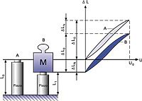
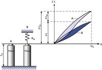
Displacement is reduced For piezo actuator operation against an elastic load different rules apply. Part of the displacement generated by the piezo effect is lost due to the elasticity of the piezo element (Fig. 21). The total available displacement can be related to the spring stiffness by the following equations:
(Equation 6)
Maximum displacement of a piezo actuator acting against a spring load.
(Equation 7)
Maximum loss of displacement due to external spring force. In the case where the restraint is infinitely rigid (ks = ∞), the piezo actuator can produce no displacement but acts only as a force generator.
Where:
DL = displacement with external spring load [m] DL0 = nominal displacement without external force or restraint [m] DLR = lost displacement caused by the external spring [m] ks = spring stiffness [N/m] kT = piezo actuator stiffness [N/m]
Example Q: What is the maximum displacement of a 15 µm piezo translator with a stiffness of 50 N/µm, mounted in an elastic restraint with a spring constant kS (stiffness) of 100 N/µm?
A: Equation 6 shows that the displacement is reduced in an elastic restraint. The spring constant of the external restraint is twice the value of the piezo translator. The achievable displacement is therefore limited to 5 µm (1/3 of the nominal travel).
Drawings & Images:
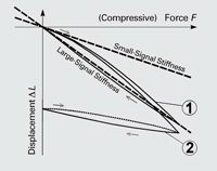
Fig. 18. Quasi-static characteristic mechanical stress/strain curves for piezo ceramic actuators and the derived stiffness values. Curve 1 is with the nominal operating voltage on the electrodes, Curve 2 is with the electrodes shorted (showing ceramics after depolarization)
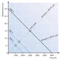
Fig. 19. Force generation vs. displacement of a piezo actuator (displacement 30 µm, stiffness 200 N/µm). Stiffness at various operating voltages. The points where the dashed lines (external spring curves) intersect the piezo actuator force/displacement curves determine the force and displacement for a given setup with an external spring. The stiffer the external spring (flatter dashed line), the less the displacement and the greater the force generated by the actuator. Maximum work can be done when the stiffness of the piezo actuator and external spring are identical.
Fig. 20. Case a: Zero-point offset with constant force.
Fig. 21. Case b: Effective displacement of a piezo actuator acting against a spring load.
Dynamic Forces Every time the piezo drive voltage changes, the piezo element changes its dimensions. Due to the inertia of the piezo actuator mass (plus any additional load), a rapid move will generate a force acting on (pushing or pulling) the piezo. The maximum force that can be generated is equal to the blocked force, described by:
(Equation 8)
Maximum force available to accelerate the piezo mass plus any additional load. Tensile forces must be compensated, for example, by a spring preload.
Where:
Fmax = max. force [N]
DL0 = max. nominal displacement without external force or restraint [m]
kT = piezo actuator stiffness [N/m]
The preload force should be around 20% of the compressive load limit. The preload should be soft compared to the piezo actuator, at most 10% the actuator stiffness. In sinusoidal operation peak forces can be expressed as:
(Equation 9)
Dynamic forces on a piezo actuator in sinusoidal operation at frequency f.
Where:
Fdyn = dynamic force [N] meff = effective mass [kg], DL = peak-to-peak displacement [m] f = frequency [Hz]
The maximum permissible forces must be considered when choosing an operating frequency.
Example: Dynamic forces at 1000 Hz, 2 m peak-to-peak and 1 kg load reach approximately ±40 N.
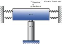
Note A guiding system (e.g. diaphragm type) is essential when loads which are heavy or large (relative to the piezo actuator diameter) are moved dynamically. Without a guiding system, there is a potential for tilt oscillations that may damage the piezoceramics.
Resonant Frequency In general, the resonant frequency of any spring/mass system is a function of its stiffness and effective mass (see Fig. 23). Unless otherwise stated, the resonant frequency given in the technical data tables for actuators always refer to the unloaded actuator with one end rigidly attached. For piezo positioning systems, the data refers to the unloaded system firmly attached to a significantly larger mass.
(Equation 10)
Resonant frequency of an ideal spring/mass system.
Where:
fO = resonant frequency of unloaded actuator [Hz]
kT = piezo actuator stiffness [N/m]
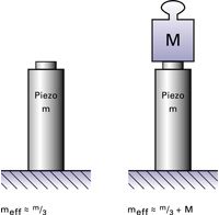
meff = effective mass (about 1/3 of the mass of the ceramic stack plus any installed end pieces) [kg]
Note: In positioning applications, piezo actuators are operated well below their resonant frequencies. Due to the non-ideal spring behavior of piezoceramics, the theoretical result from the above equation does not necessarily match the real-world behavior of the piezo actuator system under large signal conditions. When adding a mass M to the actuator, the resonant frequency drops according to the following equation:
(Equation 11)
Resonant frequency with added mass.
m´eff = additional mass M + meff.
The above equations show that to double the resonant frequency of a spring-mass system, it is necessary to either increase the stiffness by a factor of 4 or decrease the effective mass to 25 % of its original value. As long as the resonant frequency of a preload spring is well above that of the actuator, forces it introduces do not significantly affect the actuator"s resonant frequency.
The phase response of a piezo actuator system can be approximated by a second order system and is described by the following equation:
(Equation 12)
Where:
j = phase angle [deg]
Fmax = resonant frequency [Hz]
f = operating frequency [Hz]
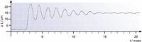
How Fast Can a Piezo Actuator Expand? Fast response is one of the characteristic features of piezo actuators. A rapid drive voltage change results in a rapid position change. This property is especially welcome in dynamic applications such as scanning microscopy, image stabilization, switching of valves/shutters, shock-wave generation, vibration cancellation systems, etc.
A piezo actuator can reach its nominal displacement in approximately 1/3 of the period of the resonant frequency, provided the controller can deliver the necessary current. If not compensated by appropriate measures (e.g. notch filter, InputShaping®) in the servo-loop, such rapid expansion will be accompanied by significant overshoot.
(Equation 13)
Minimum rise time of a piezo actuator (requires an amplifier with sufficient output current and slew rate).
Where:
Tmin = time [s]
f0 = resonant frequency [Hz]]
Example: A piezo translator with a 10 kHz resonant frequency can reach its nominal displacement within 30 µs.
Drawings & Images:
Fig. 22. Recommended guiding for large masses.
Fig. 23. Effective mass of an actuator fixed at one end.
Fig. 24. Response of an undamped, lever-amplified piezo actuator (low resonant frequency) to a rapid drive-voltage change. This behavior can be prevented by intelligent control techniques or position servo-control.
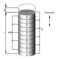
General When operated well below the resonant frequency, a piezo actuator behaves as a capacitor: The actuator displacement is proportional to stored charge (first order estimate). The capacitance of the actuator depends on the area and thickness of the ceramic, as well as on its material properties. For piezo stack actuators, which are assembled with thin, laminar wafers of electroactive ceramic material electrically connected in parallel, the capacitance also depends on the number of layers.
The small-signal capacitance of a stack actuator can be estimated by:
(Equation 14)
Where:
C = capacitance [F (As/V)]
n = number of layers =
ε33T = dielectric constant [As/Vm]
A = electrode surface area of a single layer [m2]
dS = distance between the individual electrodes (layer-thickness) [m] I0 = actuator length
The equation shows that for a given actuator length, the capacitance increases with the square of the number of layers. Therefore, the capacitance of a piezo actuator constructed of 100 µm thick layers is 100 times the capacitance of an actuator with 1 mm layers, if the two actuators have the same dimensions. Although the actuator with thinner layers draws 100 times as much current, the power requirements of the two actuators in this example are about the same. The PI high-voltage and low-voltage amplifiers in this catalog are designed to meet the requirements of the respective actuator types.
Static Operation When electrically charged, the amount of energy stored in the piezo actuator is E = (1/2) CU2 Every change in the charge (and therefore in displacement) of the PZT ceramics requires a current i:
(Equation 15)
Relationship of current and voltage for the piezo actuator
Where:
i = current [A]
Q = charge [coulomb (As)]
C = capacitance [F]
U = voltage [V]
t = time [s]
For static operation, only the leakage current need be supplied. The high internal resistance reduces leakage currents to the micro-amp range or less. Even when suddenly disconnected from the electrical source, the charged actuator will not make a sudden move, but return to its uncharged dimensions very slowly.
For slow position changes, only very low current is required.
Example: An amplifier with an output current of 20 µA can fully expand a 20 nF actuator in one second. Suitable amplifiers can be found using the Control Electronics Selection Guide.
Note The actuator capacitance values indicated in the technical data tables are small-signal values (measured at 1 V, 1000 Hz, 20 °C, unloaded) The capacitance of piezoceramics changes with amplitude, temperature, and load, to up to 200 % of the unloaded, small-signal, room-temperature value. For detailed information on power requirements, refer to the amplifier frequency response curves in the Piezo Drivers & Nanopositioning Controllers section.
Dynamic Operation (Linear) Piezo actuators can provide accelerations of thousands of g’s and are ideally suited for dynamic applications.
Several parameters influence the dynamics of a piezo positioning system:
The slew rate [V/s] and the maximum current capacity of the amplifier limit the operating frequency of the piezo system.
If sufficient electrical power is available from the amplifier, the maximum drive frequency may be limited by dynamic forces (Dynamic Operation).
In closed-loop operation, the maximum operating frequency is also limited by the phase and amplitude response of the system. Rule of thumb: The higher the system resonant frequency, the better the phase and amplitude response, and the higher the maximum usable frequency. The sensor bandwidth and performance of the servo-controller (digital and analog filters, control algorithm, servo-bandwidth) determine the maximum operating frequency of a piezoelectric system.
In continuous operation, heat generation can also limit the operating frequency. The following equations describe the relationship between amplifier output current, voltage and operating frequency. They help determine the minimum specifications of a piezo amplifier for dynamic operation.
(Equation 16)
Long-term average current required for sinusoidal operation
(Equation 17)
Peak current required for sinusoidal operation
(Equation 18)
Maximum operating frequency with triangular waveform, as a function of the amplifier output current limit
Where:
ia* = average amplifier source/sink current [A]
imax* = peak amplifier source/sink current [A]
fmax = maximum operating frequency [Hz]
C** = piezo actuator capacitance [Farad (As/V)]
Up-p = peak-to-peak drive voltage [V]
f operating frequency [Hz]
The average and maximum current capacity for each PI piezo amplifier can be found in the product technical data tables.
Example Q: What peak current is required to obtain a sinewave displacement of 20 µm at 1000 Hz from a 40 nF HVPZT actuator with a nominal displacement of 40 µm at 1000V?
A: The 20 µm displacement requires a drive voltage of about 500 V peak-to-peak. With Equation 17 the required peak current is calculated at » 63 mA. For appropriate amplifiers, see Piezo Drivers & Nanopositioning Controllers.
The following equations describe the relationship between (reactive) drive power, actuator capacitance, operating frequency and drive voltage.
The average power a piezo driver has to be able to provide for sinusoidal operation is given by:
(Equation 19)
Peak power for sinusoidal operation is:
(Equation 20)
Where:
Pa = average power [W] Pmax = peak power [W] C** = piezo actuator capacitance [F] f = operating frequency [Hz] Up-p = peak-to-peak drive voltage [V] Umax = nominal voltage of the amplifier [V]
It is also essential that the power supply be able to supply sufficient current.
* The power supply must be able to provide enough current. ** For large-signal conditions a margin of 70% of the small-signal value should be added.
Dynamic Operating Current Coefficient (DOCC) Instead of calculating the required drive power for a given application, it is easier to calculate the drive current, because it increases linearly with both frequency and voltage (displacement). For this purpose, the Dynamic Operating Current Coefficient (DOCC) has been introduced. The DOCC is the current that must be supplied by the amplifier to drive the piezo actuator per unit frequency (Hz) and unit displacement. DOCC values are valid for sinewave operation in open-loop mode. In closed-loop operation the current requirement can be up to 50% higher.
The peak and long-term average current capacities of the different piezo amplifiers can be found in the technical data tables for the electronics, the DOCC values in the tables for the piezo actuators.
Example: To determine whether a selected amplifier can drive a given piezo actuator at 50 Hz with 30 µm peak-to-peak displacement, multiply the actuator’s DOCC by 50 x 30 and compare the result with the average output current of the selected amplifier. If the current required is less than or equal to the amplifier output, then the amplifier has sufficient capacity for the application.
Dynamic Operation (Switched) For applications such as shock wave generation or valve control, switched operation (on / off) may be sufficient. Piezo actuators can provide motion with rapid rise and fall times with accelerations in the thousands of g’s. For information on estimating the forces involved, see Dynamic Forces.
The simplest form of binary drive electronics for piezo applications would consist of a large capacitor that is slowly charged and rapidly discharged across the PZT ceramics.
The following equation relates applied voltage (which corresponds to displacement) to time.
(Equation 21)
Voltage on the piezo after switching event.
Where:
U0 = start voltage [V]
Up-p = source output voltage (peak-to-peak) [V]
R = source output resistance [ohm]
C = piezo actuator capacitance [F]
t = time [s]
The voltage rises or falls exponentially with the RC time constant. Under quasi-static conditions, the expansion of the PZT ceramics is proportional to the voltage. In reality, dynamic piezo processes cannot be described by a simple equation. If the drive voltage rises too quickly, resonance occurs, causing ringing and overshoot. Furthermore, whenever the piezo actuator expands or contracts, dynamic forces act on the ceramic material. These forces generate a (positive or negative) voltage in the piezo element which is superimposed on the drive voltage. A piezo actuator can reach its nominal displacement in approximately 30 % of the period of the resonant frequency, provided the controller can deliver the necessary current.
The following equation applies for constant-current charging (as with a linear amplifier):
(Equation 22)
Time to charge a piezoceramic with constant current. With lower-capacity electronics, amplifier slew rate can be a limiting factor.
Where:
t = time to charge piezo to Up-p [s]
C = piezo actuator capacitance [F]
Up-p = voltage change (peak-to-peak) [V]
imax = peak amplifier source/sink current [A]
For fastest settling, switched operation is not the best solution because of the resulting overshoot. Modern techniques like InputShaping® solve the problem of resonances in and around the actuator with complex signal processing algorithms.
Note Piezo drives are becoming more and more popular because they can deliver extremely high accelerations. This property is very important in applications such as beam steering and optics stabilization. Often, however, the actuators can accelerate faster than the mechanics they drive can follow. Rapid actuation of nanomechanisms can cause recoil-generated ringing of the actuator and any adjacent components. The time required for this ringing to damp out can be many times longer than the move itself. In time-critical industrial nanopositioning applications, this problem obviously grows more serious as motion throughputs increase and resolution requirements tighten.
Classical servo-control techniques cannot solve this problem, especially when resonances occur outside the servo-loop such as when ringing is excited in a sample on a fast piezo scanning stage as it reverses direction. A solution is often sought in reducing the scanning rate, thereby sacrificing part of the advantage of a piezo drive.
A patented real-time feedforward technology called InputShaping® nullifies resonances both inside and outside the servo-loop and thus eliminates the settling phase. More information here.
Heat Generation in a Piezo Actuator in Dynamic Operation PZT ceramics are (reactive) capacitive loads and therefore require charge and discharge currents that increase with operating frequency. The thermal active power, P (apparent power x power factor, cos j), generated in the actuator during harmonic excitation can be estimated with the following equation:
(Equation 23)
Heat generation in a piezo actuator.
Where:
P = power converted to heat [W]
tan d = dielectric factor (» power factor, cos j, for small angles d and j)
f = operating frequency [Hz]
C = actuator capacitance [F]
Up-p = voltage (peak-to-peak)
For the description of the loss power, we use the loss factor tan d instead of the power factor cos j, because it is the more common parameter for characterizing dielectric materials. For standard actuator piezoceramics under small-signal conditions the loss factor is on the order of 0.01 to 0.02. This means that up to 2 % of the electrical power flowing through the actuator is converted into heat. In large-signal conditions however, 8 to 12 % of the electrical power pumped into the actuator is converted to heat (varies with frequency, temperature, amplitude etc.). Therefore, maximum operating temperature can limit the piezo actuator dynamics. For large amplitudes and high frequencies, cooling measures may be necessary. A temperature sensor mounted on the ceramics is suggested for monitoring purposes.
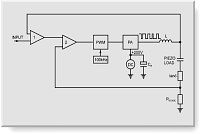
For higher frequency operation of high-load actuators with high capacitance (such as PICA™-Power actuators), a special amplifiers employing energy recovery technology has been developed. Instead of dissipating the reactive power at the heat sinks, only the active power used by the piezo actuator has to be delivered.
The energy not used in the actuator is returned to the amplifier and reused, as shown in the block diagram in Fig. 26. The combination of low-loss, high-energy piezoceramics and amplifiers with energy recovery are the key to new high-level dynamic piezo actuator applications.
For dynamic applications with low to medium loads, the newly developed PICMA® actuators are also quite well suited. With their high Curie temperature of 320 °C, they can be operated with internal temperatures of up to 150 °C.
Piezoceramic Manifacturing Process / Video
Drawings & Images:
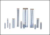
Fig. 25. Design of a piezo stack actuator.
Fig. 26. Block diagram of an amplifier with energy recovery for higher frequency applications.