|
|
|
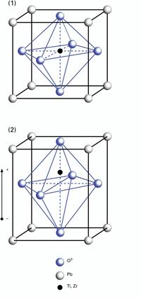
Displacement of Piezo Actuators (Stack & Contraction Type)
Commonly used stack actuators achieve a relative displacement of up to 0.2 %. Displacement of piezoceramic actuators is primarily a function of the applied electric field strength E, the length L of the actuator, the forces applied to it and the properties of the piezoelectric material used. The material properties can be described by the piezoelectric strain coefficients dij. These coefficients describe the relationship between the applied electric field and the mechanical strain produced.
The change in length, DL, of an unloaded single-layer piezo actuator can be estimated by the following equation:
(Equation 1)
Where:
S = strain (relative length change DL/L, dimensionless)
L0 = ceramic length [m]
E = electric field strength [V/m]
dij = piezoelectric coefficient of the material [m/V]
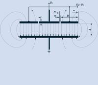
d33 describes the strain parallel to the polarization vector of the ceramics (thickness) and is used when calculating the displacement of stack actuators; d31 is the strain orthogonal to the polarization vector (width) and is used for calculating tube and strip actuators (see Fig. 9). d33 and d31 are sometimes referred to as piezo gain.
Notes
For the materials used in standard PI piezo actuators, d33 is on the order of 250 to 550 pm/V, d31 is on the order of -180 to -210 pm/V. The highest values are attainable with shear actuators in d15 mode. These figures only apply to the raw material at room temperature under small-signal conditions.
The maximum allowable field strength in piezo actuators is between 1 and 2 kV/mm in the polarization direction. In the reverse direction (semi-bipolar operation), at most 300 V/mm is allowable (see Fig. 10). The maximum voltage depends on the ceramic and insulation materials.
Exceeding the maximum voltage may cause dielectric breakdown and irreversible damage to the piezo actuator.
With the reverse field, negative expansion (contraction) occurs, giving an additional 20 % of the nominal displacement. If both the regular and reverse fields are used, a relative expansion (strain) up to 0.2 % is achievable with piezo stack actuators. This technique can reduce the average applied voltage without loss of displacement and thereby increase piezo lifetime.
Stacks can be built with aspect ratios up to 12:1 (length:diameter). This means that the maximum travel range of an actuator with 15 mm piezo diameter is limited to about 200 µm. Longer travel ranges can be achieved by mechanical amplification techniques (see Lever Motion Amplifiers ).
Note:
PI piezo actuators and stages are designed for high reliability in industrial applications. The travel, voltage and load ranges in the technical data tables can actually be used in practice. They have been collected over many years of experience in piezo actuator production and in numerous industrial applications.
In contrast to many other piezo suppliers, PI has its own piezo ceramic development and production facilities together with the necessary equipment and knowhow. The goal is always reliability and practical usefulness. Maximizing isolated parameters, such as expansion or stiffness, at the cost of piezo lifetime might be interesting to an experimenter, but has no place in practical application.
When selecting a suitable piezo actuator or stage, consider carefully the fact that maximum travel may not be the only critical design parameter.
Hysteresis (Open-Loop Piezo Operation)
Hysteresis is observable in open-loop operation; it can be reduced by charge control and virtually eliminated by closed-loop operation (see pp. see link ff.).
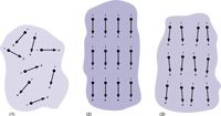
Open-loop piezo actuators exhibit hysteresis in their dielectric and electromagnetic large-signal behavior. Hysteresis is based on crystalline polarization effects and molecular effects within the piezoelectric material.
The amount of hysteresis increases with increasing voltage (field strength) applied to the actuator. The gap in the voltage/displacement curve (see Fig. 11) typically begins around 2 % (small-signal) and widens to a maximum of 10 % to 15 % under large-signal conditions. The highest values are attainable with shear actuators in d15 mode.
For example, if the drive voltage of a 50 µm piezo actuator is changed by 10 %, (equivalent to about 5 µm displacement) the position repeatability is still on the order of 1 % of full travel or better than 1 µm.
The smaller the move, the smaller the uncertainty. Hysteresis must not be confused with the backlash of conventional mechanics. Backlash is virtually independent of travel, so its relative importance increases for smaller moves.
For tasks where it is not the absolute position that counts, hysteresis is of secondary importance and open-loop actuators can be used, even if high resolution is required.
In closed-loop piezo actuator systems hysteresis is fully compensated. PI offers these systems for applications requiring absolute position information, as well as motion with high linearity, repeatability and accuracy in the nanometer and sub-nanometer range (see pp. see link ff.).
Example: Piezoelectrically driven fiber aligners and tracking systems derive the control signal from an optical power meter in the system. There, the goal is to maximize the optical signal level as quickly as possible, not to attain a predetermined position value. An open-loop piezo system is sufficient for such applications. Advantages like unlimited resolution, fast response, zero backlash and zero stick/slip effect are most welcome, even without position control.
Creep / Drift (Open-Loop Piezo Operation)
The same material properties responsible for hysteresis also cause creep or drift. Creep is a change in displacement with time without any accompanying change in the control voltage. If the operating voltage of a piezo actuator is changed, the remnant polarization (piezo gain) continues to change, manifesting itself in a slow change of position. The rate of creep decreases logarithmically with time (see Fig. 12). The following equation describes this effect:
(Equation 2)

Creep of PZT motion as a function of time.
Where:
t = time [s]
DL(t) = change in position as a function of time
DLt= 0.1 = displacement 0.1 seconds after the voltage change is complete [m].
g = creep factor, which is dependent on the properties of the actuator (on the order of 0.01 to 0.02, which is 1 % to 2 % per time decade).
In practice, maximum creep (after a few hours) can add up to a few percent of the commanded motion.
Aging
Aging refers to reduction in remnant polarization; it can be an issue for sensor or charge-generation applications (direct piezo effect). With actuator applications it is negligible, because repoling occurs every time a higher electric field is applied to the actuator material in the poling direction.
Note
For periodic motion, creep and hysteresis have only a minimal effect on repeatability.
|
|
|
 |
| Drawings & Images: |
| |
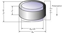
Fig. 9. Expansion and contraction of a piezoelectric disk in response to an applied voltage. Note that d31, which describes the lateral motion, DD, is negative.
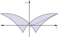
Fig. 10. Typical response of a soft PZT actuator to a bipolar drive voltage. When a certain threshold voltage negative to the polarization direction is exceeded, reversal of polarization can occur.
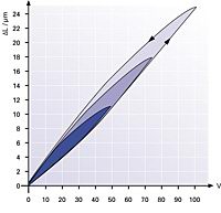
Fig. 11. Hysteresis curves of an open-loop piezo actuator for various peak voltages. The hysteresis is related to the distance moved, not to the nominal travel range.
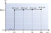
Fig. 12. Creep of open-loop PZT motion after a 60 µm change in length as a function of time. Creep is on the order of 1 % of the last commanded motion per time decade.
|
|
|