Piezo Mechanisms: Parallel and Serial Kinematics / Metrology


Actuators | Piezo Motors | Piezo Transducer | Piezo Stages | Controllers | FSM

Direct and Indirect Metrology

Note / Additional Information:
Piezo Application Examples
are found in the Piezo Blog


Video Animations of
Different Piezo Motion Technologies


Non-contact sensors are used to obtain the most accurate position values possible for position servo-control systems. Two-plate capacitive sensors installed directly on the moving platform and measuring on the axis of motion offer the best performance. Resolution and repeatability can attain 0.1 nanometer in such systems. Indirect metrology—measuring strain at some point in the drive train—cannot be used in systems with the highest accuracy requirements.

Parallel and Serial Kinematics
There are two basic ways to design multi-axis positioning systems: Serial kinematics and parallel kinematics. Serial kinematics are easier to design and build and can be operated with simpler controllers. They do, however, have a number of disadvantages compared to higher-performance and more elegant parallel kinematics systems. In a multi-axis serial kinematics system, each actuator is assigned to exactly one degree of freedom. If there are integrated position sensors, they are also each assigned to one drive and measure only the motion caused by that drive and in its direction of motion. All undesired motion (guiding error) in the other five degrees of freedom are not seen and hence cannot be corrected in the servo-loop, which leads to cumulative error.

In a parallel kinematics multi-axis system, all actuators act directly on the same moving platform.
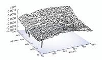
Only in this way can the same resonant frequency and dynamic behavior be obtained for the X and Y axes. It is also easy to implement parallel metrology in parallel kinematics systems. A parallel metrology sensor sees all motion in its measurement direction, not just that of one actuator, so runout from all actuators can be compensated in real-time (active trajectory control). The results are significantly less deviation from the ideal trajectory, better repeatability and flatness, as shown in Fig. 51.

Examples:
P-734 Ultra-Precision Trajectory, XY Nanopositioning Stages with Parallel Metrology, and P-587 Six-Axis, Ultra-High-Precision 6 Axis Nano-Positioning Stage, Piezo-Driven, with Parallel Metrology

Drawings & Images:
 

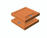
Fig. 50 a. Working principle of a stacked XY piezo stage (serial kinematics). Advantages: Modular, simple design. Disadvantages compared with parallel kinematics: More inertia, higher center of gravity, moving cables (can cause friction and hysteresis). Integrated parallel metrology and active trajectory control (automatic off-axis error correction) are not possible.


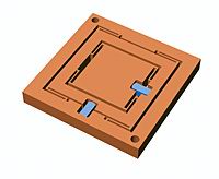
Fig. 50 b. Working principle of a nested XY piezo stage (serial kinematics). Lower center of gravity and somewhat better dynamics compared with stacked system, but retains all the other disadvantages of a stacked system, including asymmetric dynamic behavior of X and Y axes.

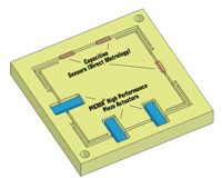
Fig. 50 c. Working principle of a monolithic XY<font face=symbol>q</font><sub>Z</sub> parallel kinematics piezo stage. All actuators act directly on the central platform. Integrated parallel metrology keeps all motion in all controlled degrees of freedom inside the servo-loop. The position of the central, moving platform is measured directly with capacitive sensors, permitting all deviations from the prescribed trajectory to be corrected in real-time. This feature, called active trajectory control, is not possible with serial metrology.
Fig. 50 c. Working principle of a monolithic XYqZ parallel kinematics piezo stage. All actuators act directly on the central platform. Integrated parallel metrology keeps all motion in all controlled degrees of freedom inside the servo-loop. The position of the central, moving platform is measured directly with capacitive sensors, permitting all deviations from the prescribed trajectory to be corrected in real-time. This feature, called active trajectory control, is not possible with serial metrology.


Fig. 51. Flatness (Z-axis) of a 6-axis nanopositioning system with active trajectory control over a 100 x 100 µm scanning range. The moving portion of this parallel metrology positioner is equipped with ultra-precise parallel metrology capacitive sensors in all six degrees of freedom. The sensors are continually measuring the actual position against the stationary external reference.

A digital controller compares the six coordinates of the actual position with the respective target positions. In addition to controlling the scanning motion in the X and Y directions, the controller also ensures that any deviations that occur in the other four degrees of freedom are corrected in real-time.


Related Information:
 
Piezo Stage
Multi-Axis, Piezo Nanopositioning / Scanning Stages with Parallel Metrology
 
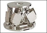
Hexapods
Compact 6-Axis Parallel Kinematics Positioning and Alignment System


to the top

Different Electro-Ceramic Materials: PMN Compared to PZT


Electrostrictive Actuators (PMN)
Electrostrictive actuators operate on a principle similar to that of PZT actuators. The electrostrictive effect can be observed in all dielectric materials, even in liquids.

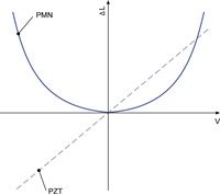
Electrostrictive actuators are made of an unpolarized lead magnesium niobate (PMN) ceramic material. PMN is a ceramic exhibiting displacement proportional to the square of the applied voltage under small-signal conditions. Under these conditions PMN unit cells are centro-symmetric at zero volts. An electrical field separates the positively and negatively charged ions, changing the dimensions of the cell and resulting in an expansion. Electrostrictive actuators must be operated above the Curie temperature, which is typically very low when compared to PZT materials.

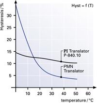
The quadratic relationship between drive voltage and displacement means that PMN actuator are intrinsically nonlinear, in contrast to PZT actuators. PMN actuators have an electrical capacitance several times as high as piezo actuators and hence require higher drive currents for dynamic applications. However, in a limited temperature range, electrostrictive actuators exhibit less hysteresis (on the order of 3 %) than piezo actuators. An additional advantage is their greater ability to withstand pulling forces.

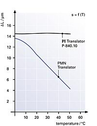
PZT materials have greater temperature stability than electrostrictive materials, especially with temperature variations of over 10 °C.

As temperature increases, available travel is reduced; at low temperatures where travelis greatest hysteresis increases (see Fig. 53 b). PMN actuators are thus best for applications with little or no temperature variations of the ceramic, be they caused by dynamic operation or by environmental factors.

Summary

Piezoelectric actuators offer a solution to many positioning tasks that depend on highest accuracy, speed and resolution.

Examples given in this tutorial indicate a selection of the many applications common today. The relentless push for more accuracy and speed—whether in the further miniaturization of microelectronics, production of optics and higher-performance data storage devices, precise positioning of optical fiber components for telecommunications, or in the fabrication of micromechanisms—drives both the application and the further development of piezo technology.

To use the advantages of piezo positioners to their full extent, it is important to carefully analyze the system in which a piezo actuator is used as a whole. Close contact between user and manufacturer is the best recipe for success.

Piezoelectric actuators will in the future partially replace, partially complement, conventional drive technologies. They will widen the realm of the possible, and will usher in developments in areas like nanotechnology which would be unthinkable with conventional drive technologies.

Drawings & Images:
 
Fig. 52. Comparison of PMN and PZT material: displacement as a function of field strength (generalized).

Fig. 53 a. Comparison of PMN and PZT material: displacement as a function of temperature.

Fig. 53 b. Comparison of PMN and PZT material: hysteresis as a function of temperature.


Related Information:
 
P-882 – P-888
PICMA® High-Performance Monolithic Multilayer Piezo Actuators (LVPZT)


to the top

Mounting Guidelines for Piezo Translators

>> Piezo Stack Actuator Product Overview

Adherence to the following guidelines will help you obtain maximum performance and lifetime from your piezo actuators: Do not use metal tools for actuator handling. Do not scratch the coating on the side surfaces. The following precautions are recommended during handling of piezoelectric actuators:

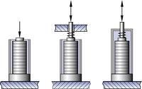
I. Piezoelectric stack actuators without axial preload are sensitive to pulling forces. A preload of up to 50% of the blocking force is generally recommended.

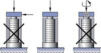
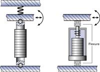
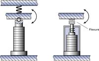
II. Piezoelectric stack actuators may be stressed in the axial direction only. The applied force must be centered very well. Tilting and shearing forces, which can also be induced by parallelism errors of the endplates, have to be avoided because they will damage the actuator. This can be ensured by the use of ball tips, flexible tips, adequate guiding mechanisms etc. An exception to this requirement is made for the PICA™-Shear actuators, because they operate in the shear direction.

III. Piezoelectric stack actuators can be mounted by gluing them between even metal or ceramic surfaces by a cold or hot curing epoxy, respectively. Ground surfaces are preferred. Please, do not exceed the specified working temperature range of the actuator during curing.

IV. The environment of all actuators should be as dry as possible. PICMA® actuators are guarded against humidity by their ceramic coating. Other actuators must be protected by other measures (hermetic sealing, dry air flow, etc).

The combination of longterm high electric DC fields and high relative humidity values should be avoided with all piezoelectric actuators.

V. It is important to shortcircuit the piezoelectric stack actuators during any handling operation. Temperature changes and load changes will induce charges on the stack electrodes which might result in high electric fields if the leads are not shorted: Should the stack become charged, rapid discharging—especially without a preload—might damage the stack. Use a resistor for discharging.

VI. Prevent any contamination of the piezo ceramic surfaces with conductive or corrosive substances. Isopropanol is recommended for cleaning. Avoid acetone and excessive ultrasonic cleaning at higher temperatures.

Mounting Guidelines Drawings & Images:
 
Fig. 54. No pulling force without preload. Fig. 55. No lateral force or torque
Fig. 54. No pulling force without preload.Fig. 55. No lateral force or torque
 
Fig. 56. Ball tips or flexures to decouple lateral forces Fig. 57. Ball tips or flexures to decouple bending forces Fig. 58. Bolting of both ends is not recommended The slightest misalignment can lead to excessive stress on the ceramic.