Piezo Mechanims: Servo Control & Different Designs


Actuators | Piezo Motors | Piezo Transducer | Piezo Stages | Controllers | FSM
Position Servo-Control

Note / Additional Information:
Piezo Application Examples
are found in the Piezo Blog


Video Animations of
Different Piezo Motion Technologies


Position servo-control eliminates nonlinear behavior of piezoceramics such as hysteresis and creep and is the key to highly repeatable nanometric motion.

PI offers the largest selection of closed-loop piezo mechanisms and control electronics worldwide. The advantages of position servo-control are:

  • High linearity, stability, repeatability and accuracy
  • Automatic compensation for varying loads or forces
  • Virtually infinite stiffness (within load limits)
  • Elimination of hysteresis and creep effects

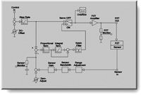
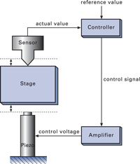
PI closed-loop piezo actuators and systems are equipped with position measuring systems providing sub-nanometer resolution, linearity to 0.01 %, and bandwidths up to 10 kHz. A servo-controller (digital or analog) determines the output voltage to the PZT ceramics by comparing a reference signal (commanded position) to the actual sensor position signal (see Fig. 28).

For maximum accuracy, it is best if the sensor measures the motion of the part whose position is of interest (direct metrology). PI offers a large variety of piezo actuators with integrated direct-metrology sensors. Capacitive sensors provide the best accuracy (see section 5, “Capacitive Position Sensors”). Simpler, less accurate systems measure things like strain in drive elements.


Open- and Closed-Loop Resolution
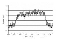
Position servo-controlled piezo drives offer linearity and repeatability many times better than that of open-loop systems. The resolution (minimum incremental motion) of piezo actuators is actually better for open-loop than for closed-loop systems. This is because piezo resolution is not limited by friction but rather by electronic noise. In open-loop, there is no sensor or servo-electronics to put additional noise on the control signal. In a servo-controlled piezo system, the sensor and control electronics are thus of considerable importance. With appropriate, high-quality systems, subnanometer resolution is also possible in closed-loop mode, as can be seen in Fig. 30 and 31. Capacitive sensors attain the highest resolution, linearity and stability.

Piezo Calibration Data
Each PI piezo position servo-controller is calibrated with the specific closed-loop piezo positioning system to achieve optimum displacement range, frequency response and settling time. The calibration is performed at the factory and a report with plotted and tabulated positioning accuracy data is supplied with the system, such as with steering mirrors.

Digital servo piezo controllers can automatically read important calibration values from an ID-chip integrated in the piezo mechanics. This feature facilitates using a controller with various stages/actuators and vice versa.

Drawings & Images:
 
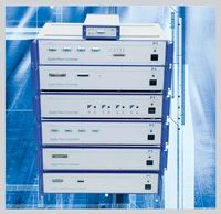
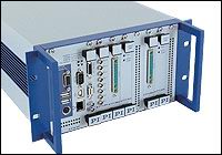
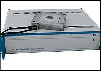
Fig. 27. Variety of digital piezo controllers.

Fig. 28. Block diagram of a typical PI closed-loop piezo positioning system.

Fig. 29. Closed-loop position servo-control. For optimum performance, the sensor is mounted directly on the object to be positioned (direct metrology).

Fig. 30. Response of a closed-loop PI piezo actuator (P-841.10, 15 µm, strain gauge sensor) to a 3 nm peak-to-peak square-wave control input signal, measured with servo-control bandwidth set to 240 Hz and 2 msec settling time. Note the crisp, backlash-free behavior in the nanometer range.

Fig. 31. PI piezo actuators with capacitive position sensors can achieve extremely high resolutions, as seen in the above result of a 250 picometer step by a S-303 phase corrector (Controller: E-509.C1A servo-controller and E-503 amplifier). The measurements were made with an ultra-sensitive capacitive sensor having a resolution of ±0.02 nm.

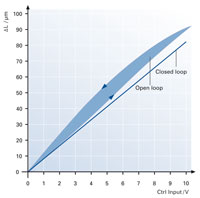
Fig. 32. Open-loop vs. closed-loop performance graph of a typical PI piezo actuator.


Related Information:
 
E-712 High-End Controller
Modular Digital Piezo Controller System, up to 6 Axes
 
E-709 Digital Piezo Controller
Cost-Efficient Controller Board for 19" Rack


Methods to Improve Piezo Dynamics


The dynamic behavior of a piezo positioning system depends on factors including the system’s resonant frequency, the position sensor and the controller used. Simple controller designs limit the usable closed-loop tracking bandwidth of a piezoelectric system to 1/10 of the system"s resonant frequency. PI offers controllers that significantly increase piezo actuator system dynamics (see table). Two of the methods are described below; additional information is available on request.

InputShaping® Stops Structural Ringing Caused by High-Throughput Motion
A patented, real-time, feedforward technology called InputShaping® nullifies resonances both inside and outside the servo-loop and virtually eliminates the settling phase. The procedure requires determination of all critical resonant frequencies in the system. A non-contact instrument like a Polytec Laser Doppler Vibrometer is especially well-suited for such measurements. The values, most importantly the resonant frequency of the sample on the platform, are then fed into the InputShaping® Signal processor. There the sophisticated signal processing algorithms assure that none of the undesired resonances in the system or its auxillary components is excited. Because the processor is outside the servo-loop, it works in open-loop operation as well.

The result: the fastest possible motion, with settling within a time equal one period of the lowest resonant frequency. InputShaping® was developed based on research at the Massachusetts Institute of Technology and commercialized by Convolve, Inc. It is an option in several PI digital piezo controllers.

Signal Preshaping / Dynamic Digital Linearization (DDL)
Signal Preshaping, a patented technique, can reduce rolloff, phase error and hysteresis in applications with repetitive (periodic) inputs. The result is to improve the effective bandwidth, especially for tracking applications such as out-of-round turning of precision mechanical or optical parts. Signal Preshaping is implemented in object code, based on an analytical approach in which the complex transfer function of the system is calculated, then mathematically transformed and applied in a feedforward manner to reduce the tracking error.

Signal Preshaping is more effective than simple phase-shifting approaches and can improve the effective bandwidth by a factor of 10 and in multi-frequency applications.

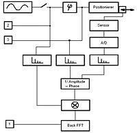
Frequency response and harmonics (caused by nonlinearity of the piezo-effect) are determined in two steps using Fast Fourier Transformation (FFT), and the results are used to calculate the new control profile for the trajectory. The new control signal compensates for the system non-linearities.

For example, it is possible to increase the command rate from 20 Hz to 200 Hz for a piezo system with a resonant frequency of 400 Hz without compromising stability. At the same time, the tracking error is reduced by a factor of about 50.


Dynamic Digital Linearization (DDL)
DDL is similar in performance to Input Preshaping, but is simpler to use. In addition, it can optimize multi-axis motion such as a raster scan or tracing an ellipse. This method requires no external metrology or signal processing, but is fully integrated in E-710 and E-711 digital controllers. DDL uses the position information from capacitive sensors integrated in the piezo mechanics (requires direct metrology) to calculate the optimum control signal. As with preshaping, the result is an improvement in linearity and tracking accuracy of up to 3 orders of magnitude.

Drawings & Images:
 
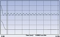
Fig. 33. InputShaping® eliminates the recoil-driven resonant reaction of loads and neighboring components due to rapid nanopositioner actuation. <br>Top: Polytec Laser Vibrometer reveals the resonant behavior of an undamped fixture when the nanomechanism is stepped. <br>Bottom: Same setup, same step, but with InputShaping®. Structural ringing is eliminated. With no excitation of vibration in the moved components, the target position is attained in a time smaller than one period of the resonant frequency.
Fig. 33. InputShaping® eliminates the recoil-driven resonant reaction of loads and neighboring components due to rapid nanopositioner actuation.
Top: Polytec Laser Vibrometer reveals the resonant behavior of an undamped fixture when the nanomechanism is stepped.
Bottom: Same setup, same step, but with InputShaping®. Structural ringing is eliminated. With no excitation of vibration in the moved components, the target position is attained in a time smaller than one period of the resonant frequency.

Fig. 34 a. Signal preshaping, phase 1.

Fig. 34 b. Signal preshaping, phase 2.

Fig. 35. No preshaping. <br>A: Control input signal (expected motion). <br>B: Actual motion of system.<br>C: Tracking error.
Fig. 35. No preshaping.
A: Control input signal (expected motion).
B: Actual motion of system.
C: Tracking error.

Fig. 36. Signal after preshaping phase 2.<br>A: Expected Motion (old control signal). <br>B: Actual motion of system. <br>C: New control input (producted by preshaping). <br>D: Tracking error.
Fig. 36. Signal after preshaping phase 2.
A: Expected Motion (old control signal).
B: Actual motion of system.
C: New control input (producted by preshaping).
D: Tracking error.

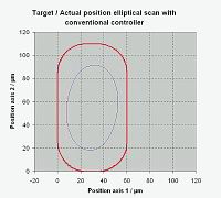
Fig. 37 a. Elliptical scan in a laser micro-drilling application with XY piezo scanning stage, conventional PID controller. The outer ellipse describes the target position, the inner ellipse shows the actual motion at the stage.

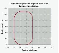
Fig. 37 b. Same scan as before, with a DDL controller. Target and actual data can hardly be discerned. The tracking error has been reduced to a few nanometers.


Related Information:
 
E-710
Multi-Channel Digital Piezo Controllers with Dynamic Linearization


Environmental Conditions and Influences


Temperature Effects

Two effects must be considered:

  • Linear Thermal Expansion
  • Temperature Dependency of the Piezo Effect

Linear Thermal Expansion
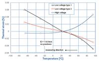
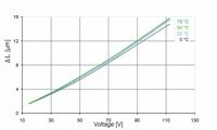
Thermal stability of piezoceramics is better than that of most other materials. Fig. 38a shows the behavior of several types of piezoceramics used by PI. The curves only describe the behavior of the piezoceramics. Actuators and positioning systems consist of a combination of piezoceramics and other materials and their overall behavior differs accordingly.

Temperature Dependency of the Piezo Effect
Piezo translators work in a wide temperature range. The piezo effect in PZT ceramics is known to function down to almost zero kelvin, but the magnitude of the piezo coefficients is temperature dependent.

At liquid helium temperature piezo gain drops to approximately 10–20% of its room-temperature value.

Piezoceramics must be poled to exhibit the piezo effect. A poled PZT ceramic may depole when heated above the maximum allowable operating temperature. The “rate” of depoling is related to the Curie temperature of the material. PI HVPZT actuators have a Curie temperature of 350 °C and can be operated at up to 150 °C. LVPZT actuators have a Curie temperature of 150 °C and can be operated at up to 80 °C. The new monolithic PICMA® ceramics with their high Curie temperature of 320 °C allow operating at temperatures of up to 150 °C.

Note
Closed-loop piezo positioning systems are less sensitive to temperature changes than open-loop systems. Optimum accuracy is achieved if the operating temperature is identical to the calibration temperature. If not otherwise specified, PI piezomechanics are calibrated at 22 °C.

Piezo Operation in High Humidity
The polymer insulation materials used in piezoceramic actuators are sensitive to humidity. Water molecules diffuse through the polymer layer and can cause short circuiting of the piezoelectric layers. The insulation materials used in piezo actuators are sensitive to humidity. For higher humidity environments, PI offers special systems with waterproofed enclosed stacks, or integrated dry-air flushing mechanisms.

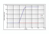
A better solution are PICMA® actuators (see Fig. 39a), which have ceramic-only insulation without any polymer covering and are thus less sensitive to water diffusion (see Fig. 39c).


Piezo Operation in Inert Gas Atmospheres
Ceramic-insulated PICMA® actuators are also recommended for use in inert gases, such as helium. To reduce the danger of flashover with high-voltage piezos, the maximum operating voltage must be reduced. Semi-bipolar operation is recommended, because the average operating voltage can be kept very low.

Vacuum Operation of Piezo Actuators
All PI piezo actuators can be operated at pressures below 100 Pa (~1 torr). When piezo actuators are used in a vacuum, two factors must be considered:

I. Dielectric stability

II. Outgassing

I. The dielectric breakdown voltage of a sample in a specific gas is a function of the pressure p times the electrode distance s. Air displays a high insulation capacity at atmospheric pressure and at very low pressures. The minimum breakdown voltage of ~300 V can be found at a ps-product of 1000 mm Pa (~10 mm torr). That is why PICMA® actuators with a maximum operating voltage of 120 V can be used in any vacuum condition. However, the operation of HVPZT actuators with dielectric layer thicknesses of 0.2 – 1.0 mm and nominal voltages to 1000 V is not recommended in the pressure range of 100 – 50000 Pa (~1 – 500 torr).

II. Outgassing behavior varies from model to model depending on design. Ultra-high-vacuum options for minimum outgassing are available for many standard low-voltage and high-voltage piezo actuators. Best suited are PICMA® ceramics (see Fig. 39a), because they have no polymers and can withstand bakeout to 150 °C.

All materials used in UHV-compatible piezo nanopositioners, including cables and connectors, are optimized for minimal outgassing rates (see Fig. 39b). Materials lists are available on request.


Lifetime of Piezo Actuators


The lifetime of a piezo actuator is not limited by wear and tear. Tests have shown that PI piezo actuators can perform billions (109) of cycles without any measurable wear.

As with capacitors, however, the field strength does have an influence on lifetime. The average voltage should be kept as low as possible. Most PI piezo actuators and electronics are designed for semi-bipolar operation.

There is no generic formula to determine the lifetime of a piezo actuator because of the many parameters, such as temperature, humidity, voltage, acceleration, load, preload, operating frequency, insulation materials, etc., which have (nonlinear) influences. PI piezo actuators are not only optimized for maximum travel, but also designed for maximum lifetime under actual operating conditions.

The operating voltage range values in the technical data tables are based on decades of experience with nanomechanisms and piezo applications in industry. Longer travel can only be obtained with higher voltages at the cost of reduced reliability.

Example:
An P-842.60 LVPZT actuator ( is to operate a switch with a stroke of 100 µm. Of its operating time, it is to be open for 70 % and closed for 30 %.

Optimum solution: The actuator should be linked to the switch in such a way that the open position is achieved with the lowest possible operating voltage. To reach a displacement of 100 µm, a voltage amplitude of approximately 110 volts is required (nominal displacement at 100 V is only 90 µm).

Since the P-842.60 can be operated down to -20 volts, the closed position should be achieved with 90 V, and the open position with -20 volts. When the switch is not in use at all, the voltage on the piezo actuator should be 0 volts.

Statistics show that most failures with piezo actuators occur because of excessive mechanical stress. Particularly destructive are tensile and shear forces, torque and mechanical shock. To protect the ceramic from such forces PI offers a variety of actuators with preloads, ball tips, flexible tips as well as custom designs.

Failures can also occur when humidity or conductive materials such as metal dust degrade the PZT ceramic insulation, leading to irreparable dielectric breakdown. In environments presenting these hazards, PICMA® actuators with their ceramic-only insulation are strongly recommended. PI also offers hermetically sealed actuators and stages.

Drawings & Images:
 
Fig. 38 a. Linear thermal expansion of different PZT ceramics.

Fig. 38 b. The expansion of PICMA® piezoceramics is only slightly temperature dependent. This, and their low heat generation, makes them ideal for dynamic applications.

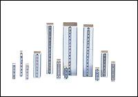
Fig. 39 a. PICMA® actuators are made with ceramic-only insulation and can dispense with any polymer coating. Result No measurable outgasing, insensitive to atmospheric humidity and a wider operating temperature range.

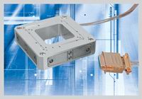
Fig. 39 b. P-733.UUD UHV-compatible XY stage for scanning microscopy applications. PICMA® ceramics are used here too. All materials used are optimized for minimal outgassing. Materials lists are available on request.

Fig. 39 c. PICMA® piezo actuators (lower curve) compared with conventional multilayer piezo actuators with polymer insulation. PICMA® actuators are insensitve to high humidity in this test. In conventional actuators, the leakage current begins to rise after only a few hours—an indication of degradation of the insulation and reduced lifetime. <br>Test conditions: U = 100 VDC, T = 25 °C, RH = 70%.
Fig. 39 c. PICMA® piezo actuators (lower curve) compared with conventional multilayer piezo actuators with polymer insulation. PICMA® actuators are insensitve to high humidity in this test. In conventional actuators, the leakage current begins to rise after only a few hours—an indication of degradation of the insulation and reduced lifetime.
Test conditions: U = 100 VDC, T = 25 °C, RH = 70%.

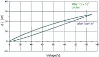
Fig. 39 d. P-885.50 PICMA® actuators with 15 MPa preload in dynamic motion test at 116 Hz. No observable wear after 1.2 billion (109) cycles.


Related Information:
 
P-882 – P-888
PICMA® High-Performance Monolithic Multilayer Piezo Actuators (LVPZT)
 
P-842 · P-843 · P-844 · P-845
Preloaded Piezo Actuators (LVPZT) with Sensor Option


Basic Designs of Piezoelectric Positioning Drives/Systems


Stack Design (Translators)
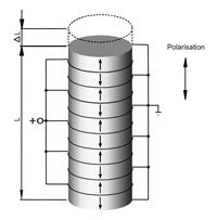
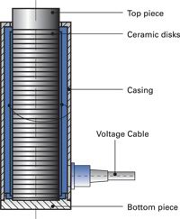
The active part of the positioning element consists of a stack of ceramic disks separated by thin metallic electrodes. The maximum operating voltage is proportional to the thickness of the disks. Most high-voltage actuators consist of ceramic layers measuring 0.4 to 1 mm in thickness. In low-voltage stack actuators, the layers are from 25 to 100 µm in thickness and are cofired with the electrodes to form a monolithic unit.

Stack elements can withstand high pressures and exhibit the highest stiffness of all piezo actuator designs. Standard designs which can withstand pressures of up to 100 kN are available, and preloaded actuators can also be operated in push-pull mode. For further information see “Maximum Applicable Forces”.

Displacement of a piezo stack actuator can be estimated by the following equation:

(Equation 24)


where:

DL = displacement [m]

d33 = strain coefficient (field and displacement in polarization direction) [m/V]

n = number of ceramic layers

U = operating voltage [V]

Example:
P-845 Actuator, etc.

Laminar Design (Contraction-Type Actuators)
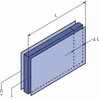
The active material in the laminar actuators consists of thin, laminated ceramic strips. The displacement exploited in these devices is that perpendicular to the direction of polarization and electric field application. When the voltage is increased, the strip contracts. The piezo strain coefficient d31 (negative!) describes the relative change in length. Its absolute value is on the order of 50 % of d33.

The maximum travel is a function of the length of the strips, while the number of strips arranged in parallel determines the stiffness and force generation of the element.

Displacement of a piezo contraction actuator can be estimated by the following equation:

(Equation 25)


where:

DL = displacement [m]

d31 = strain coefficient (displacement normal to polarization direction) [m/V]

L = length of the piezoceramics in the electric field direction [m]

U = operating voltage [V]

d = thickness of one ceramic layer [m]

Examples:
Laminar piezos can be used as contraction devices.


Tube Design
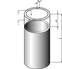
Monolithic ceramic tubes are yet another form of piezo actuator. Tubes are silvered inside and out and operate on the transversal piezo effect. When an electric voltage is applied between the outer and inner diameter of a thin-walled tube, the tube contracts axially and radially. Axial contraction can be estimated by the following equation:

(Equation 26 a)


where:

d31 = strain coefficient (displacement normal to polarization direction) [m/V]
L = length of the piezo ceramic tube [m]
U = operating voltage [V]
d = wall thickness [m]

The radial displacement is the result of the superposition of increase in wall thickness
(Equation 26 b) and the tangential contraction:

(Equation 26 b)


r = tube radius

(Equation 26 c)


where:

Dd = change in wall thickness [m]
d33 = strain coefficient (field and displacement in polarization direction) [m/V]
U = operating voltage [V]

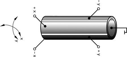
When the outside electrode of a tube is separated into four 90° segments, placing differential drive voltages ±U on opposing electrodes will lead to bending of one end. Such scanner tubes that flex in X and Y are widely used in scanning-probe microscopes, such as scanning tunneling microscopes.

The scanning range can be estimated as follows:

(Equation 27)


where:

Dx = scan range in X and Y (for symmetrical electrodes) [m]
d31 = strain coefficient (displacement normal to polarization direction) [m/V]
U = differential operating voltage [V]
L = length [m]
ID = inside diameter [m]
d = wall thickness [m]

Tube actuators cannot generate or withstand large forces. Application examples: Microdosing, nanoliter pumping, scanning microscopy, ink jet printers.

Examples:
PT120, PT130, PT140

Drawings & Images:
 
Piezo stack motion
Multilayer piezo stack actuator, animated

Fig. 40. Electrical design of a stack translator.

Fig. 41. Mechanical design of a stack translator.

Fig. 42. Laminar actuator design.

Fig. 43. Tube actuator design.

Fig. 44. Piezo scanner tube working principle.


Related Information:
 
P-007 – P-056
PICA™-Stack Piezoceramic Actuators—Versatile Piezoelectric Power (HVPZT)
 
PT120 – PT140
Piezoceramic Tubes (HVPZT)


Basic Designs of Piezoelectric Positioning Drives/Systems


Bender Type Actuators (Bimorph and Multimorph Design)
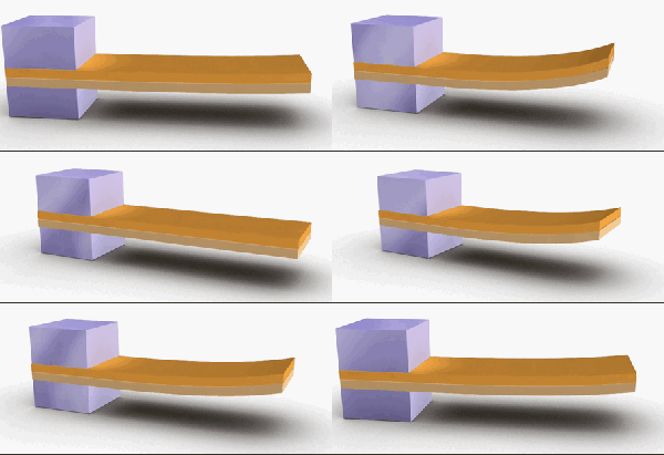
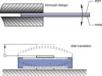
A simple bender actuator (bimorph design) consists of a passive metal substrate glued to a piezoceramic strip (see Fig.45a). A piezo bimorph reacts to voltage changes the way the bimetallic strip in a thermostat reacts to temperature changes. When the ceramic is energized it contracts or expands proportional to the applied voltage. Since the metal substrate does not change its length, a deflection proportional to the applied voltage occurs. The bimorph design amplifies the dimension change of the piezo, providing motion up to several millimeters in an extremely small package. In addition to the classical strip form, bimorph disk actuators where the center arches when a voltage is applied, are also available.

PZT/PZT combinations, where individual PZT layers are operated in opposite modes (contraction/expansion), are also available.

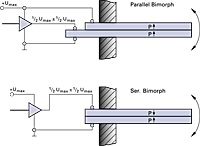
Two basic versions exist: the two-electrode bimorph (serial bimorph) and the three-electrode bimorph (parallel bimorph), as shown in Fig. 45b. In the serial type, one of the two ceramic plates is always operated opposite to the direction of polarization. To avoid depolarization, the maximum electric field is limited to a few hundred volts per millimeter. Serial bimorph benders are widely used as force and acceleration sensors.

In addition to the two-layer benders, monolithic multilayer piezo benders are also available. As with multilayer stack actuators, they run on a lower operating voltage (60 to 100 V).
Bender type actuators provide large motion in a small package at the cost of low stiffness, force and resonant frequency.

Examples:
P-286 - 289 disk translators, PL122 multilayer bender actuators

Shear Actuators
Shear actuators can generate high forces and large displacements. A further advantage is their suitability for bipolar operation, whereby the mid-position corresponds to a drive voltage of 0 V. In shear mode, unlike in the other modes, the electric field is applied perpendicular to the polarization direction. (see Fig. 46). The corresponding strain coefficient, d15, has large-signal values as high as 1100 pm/V, providing double the displacement of linear actuators of comparable size based on d33.

Shear actuators are suitable for applications like piezo linear motors, and are available as both single-axis and two-axis positioning elements.

Examples:
PX155 Shear Actuator, PicoCube, Piezo-Walk Linear Motors® motor


Piezo Actuators with Integrated Lever Motion Amplifiers
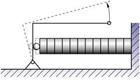
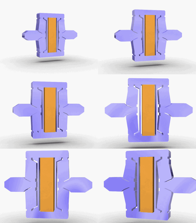
Piezo actuators or positioning stages can be designed in such a way that a lever motion amplifier is integrated into the system. To maintain sub-nanometer resolution with the increased travel range, the lever system must be extremely stiff, backlash- and friction-free, which means ball or roller bearings cannot be used. Flexures are ideally suited as linkage elements. Using flexures, it is also possible to design multi-axis positioning systems with excellent guidance characteristics.

PI employs finite element analysis (FEA) computer simulation to optimize flexure nanopositioners for the best possible straightness and flatness (see Fig. 49 and Fig. 51).

Piezo positioners with integrated motion amplifiers have both advantages and disadvantages compared to standard piezo actuators:

Advantages:

  • Longer travel
  • Compact size compared to stack actuators with equal displacement
  • Reduced capacitance (= reduced drive current)


    Disadvantages:
  • Reduced stiffness
  • Lower resonant frequency

The following relations apply to (ideal) levers used to amplify motion of any primary drive system:


where:

r = lever transmission ratio
DL0 = travel of the primary drive [m]
DLSys = travel of the lever-amplified system [m]
ksys = stiffness of the lever-amplified system [N/m]
k0 = stiffness of the primary drive system (piezo stack and joints) [N/m]
fres-sys = resonant frequency of the amplified system [Hz]
fres-0 = resonant frequency of the primary drive system (piezo stack and joints) [Hz]

Note:
The above equations are based on an ideal lever design with infinite stiffness and zero mass. They also imply that no stiffness is lost at the coupling interface between the piezo stack and the lever. In real applications, the design of a good lever requires long experience in micromechanics and nanomechanisms. A balance between mass, stiffness and cost must be found, while maintaining zero-friction and zero-backlash conditions.

Coupling the piezo stack to the lever system is crucial. The coupling must be very stiff in the pushing direction but should be soft in all other degrees of freedom to avoid damage to the ceramics. Even if the stiffness of each of the two interfaces is as high as that of the piezo stack alone, a 67 % loss of overall stiffness still results. In many piezo-driven systems, the piezo stiffness is thus not the limiting factor in determining the stiffness of the mechanism as a whole.

PI piezomechanics are optimized in this regard as a result of more than 30 years experience with micromechanics, nanopositioning and flexures.


Piezo Flexure Nanopositioners
For applications where extremely straight motion in one or more axes is needed and only nanometer or microrad deviation from the ideal trajectory can be tolerated, flexures provide an excellent solution.

A flexure is a frictionless, stictionless device based on the elastic deformation (flexing) of a solid material (e.g. steel). Sliding and rolling are entirely eliminated. In addition, flexure devices can be designed with high stiffness, high load capacity and do not wear. They are also less sensitive to shock and vibration than other guiding systems. They are also maintenance-free, can be fabricated from non-magnetic materials, require no lubricants or consumables and hence, unlike air cushion bearings, are suitable for vacuum operation.

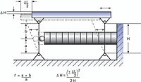
Parallelogram flexures exhibit excellent guidance characteristics. Depending on complexity and tolerances, they have straightness/flatness values in the nanometer range or better. Basic parallelogram flexures cause arcuate motion (travel in an arc) which introduces an out-of-plane error of about 0.1% of the travel range (see Fig. 48). The error can be estimated by the following equation:

(Equation 28)


where:

DH = out-of-plane error [m]

DL = distance traveled [m]

H = length of flexures [m]

For applications where this error is intolerable, PI has designed a zero-arcuate-error multi-flexure guiding system. This special design, employed in most PI flexure stages, makes possible straightness/ flatness in the nanometer or microradian range (see Fig. 49).

Note:
Flexure positioners are far superior to traditional positioners (ball bearings, crossed roller bearings, etc.) in terms of resolution, straightness and flatness. Inherent friction and stiction in these traditional designs limit applications to those with repeatability requirements on the order of 0.5 to 0.1 µm. Piezo flexure nanopositioning systems have resolutions and repeatabilities which are superior by several orders of magnitude.

Drawings & Images:
 
Piezo Bender Animation.
Piezo bender actuator, animated.

Fig. 45 a. Bimorph design (strip and disk translator).

Piezo Disk Animation
Piezo bimorph disk actuator, animated.


Fig. 45 b. Bender Actuators: Serial and parallel bimorphs.

Fig. 46. Material deformation in a shear actuator.

Fig. 46. Material deformation in a shear actuator.
Combination of shear + stack actuator, animated.

Fig. 47. Simple lever motion amplifier.

Simple piezo flexure lever animation
Simple piezo flexure lever mechanism, animatied

Fig. 48. Basic parallelogram flexure guiding system with motion amplification. The amplification r (transmission ratio) is given by (a+b)/a.

Fig. 49. Zero-arcuate-error multi-flexure guiding system.


Related Information:
 
N-111
NEXLINE® OEM Piezo Nanopositioning Stepping Drive
 
P-111 – P-151
PICA™-Shear Piezo Actuators—Compact Multiaxis Motion
 
PL112 – PL140 Multimorph Benders
PICMA® Multilayer Piezo Bender Actuators (LVPZT)
 
Mini Stages
Miniature Piezo Nanopositioning/Scanning Stage with Direct Metrology
 
PicoCube
PicoCube® High-Speed, XY(Z) Piezo Stages for Nanotechnology, SPM, AFM