|
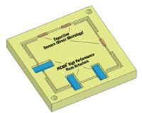
Direct and Indirect Metrology
Note / Additional Information:
Piezo Application Examples
are found in the Piezo Blog

Video Animations of
Different Piezo Motion Technologies
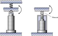
Non-contact sensors are used to obtain the most accurate position values possible for position servo-control systems. Two-plate capacitive sensors installed directly on the moving platform and measuring on the axis of motion offer the best performance. Resolution and repeatability can attain 0.1 nanometer in such systems. Indirect metrologymeasuring strain at some point in the drive traincannot be used in systems with the highest accuracy requirements.
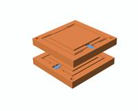
Parallel and Serial Kinematics
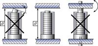
There are two basic ways to design multi-axis positioning systems: Serial kinematics and parallel kinematics. Serial kinematics are easier to design and build and can be operated with simpler controllers. They do, however, have a number of disadvantages compared to higher-performance and more elegant parallel kinematics systems. In a multi-axis serial kinematics system, each actuator is assigned to exactly one degree of freedom. If there are integrated position sensors, they are also each assigned to one drive and measure only the motion caused by that drive and in its direction of motion. All undesired motion (guiding error) in the other five degrees of freedom are not seen and hence cannot be corrected in the servo-loop, which leads to cumulative error.
In a parallel kinematics multi-axis system, all actuators act directly on the same moving platform.
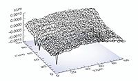
Only in this way can the same resonant frequency and dynamic behavior be obtained for the X and Y axes. It is also easy to implement parallel metrology in parallel kinematics systems. A parallel metrology sensor sees all motion in its measurement direction, not just that of one actuator, so runout from all actuators can be compensated in real-time (active trajectory control). The results are significantly less deviation from the ideal trajectory, better repeatability and flatness, as shown in Fig. 51.
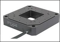
Examples:
P-734 Ultra-Precision Trajectory, XY Nanopositioning Stages with Parallel Metrology, and P-587 Six-Axis, Ultra-High-Precision 6 Axis Nano-Positioning Stage, Piezo-Driven, with Parallel Metrology
|